|
|
| Ed's kit |
ELECTRONIC DRUMKIT
|
|
| Ed's kit |
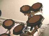
Electronic drumkits, for all their shortcomings, are great for those of us that live with a family in a neighborhood, etc., etc., i.e. around anyone that might not want to hear drums all the time. I based the drumkit around the Alesis D4 drum module which has 12 trigger inputs. I wanted a pad that was simple and cheap to build but that gave decent stick bounce, and most importantly, had even response across the pad. After much experimentation I found the solution described below. There is also another page on this site that describes my friend Ed's kit that uses a similar principle but is built around Remo practice pads for more realistic drum feel.
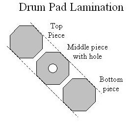
The pad is essentially a block of wood with a rubber pad on one side and a piezo transducer on the other. However, if you just glue the piezo pickup to a block of wood (or any other material I’ve tried) you get a real "hot spot" of response right above the pickup. The solution was to make the wood block hollow, so the mechanical vibration couldn’t couple as directly to the piezo pickup. The way I accomplished that was to make the wood block a laminate of 3 layers, where the middle layer has a hole cut in the middle.
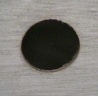
Practically speaking, what I did was to cut a bunch of 4.75 inch octagons (I like the shape and they weren’t too hard to cut) out of 1/4" hardwood plywood, like the Luaun sold at most lumber places. Then I would take 1/3 of the octagons and use a hole saw on a hand drill to cut a 2 inch hole in the middle.
Two inch hole drilled in plywood for middle layer.
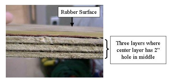
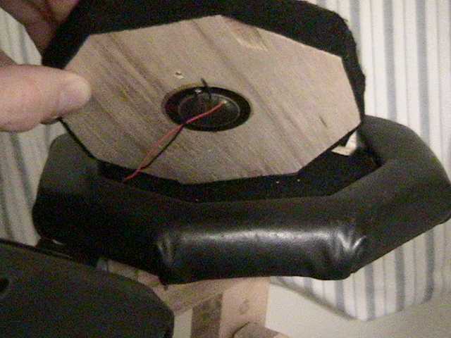
This "middle" octagon was then laminated to two "outside" octagons using carpenter’s glue to make a 3/4 inch laminate. A 1 or 1.5 inch diameter piezo element (obtained surplus from All Electronics) was then epoxied to the middle of one side, and the other side was covered with 1/4 inch rubber using contact cement. A pad made this way has remarkably even response considering how simple it is. As an alternative construction sequence, on a later build for a friend we drilled the 2 inch holes in a 2 foot by 4 foot sheet of plywood, laminated two more sheets to it, and then cut the octagons out later. You just have to be careful to plan where your holes are and include the saw cut widths in your measurements.
Lamination scheme
Piezo element glued to back of pad
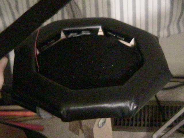
The pad's edges are covered with felt and it is placed in a "pad holder" that is made by cutting a 7 inch octagon out of 3/4 inch plywood and then cutting a 5 inch octagon out of the middle of it to fit the pad. A 7 inch octagon of 1/4 inch plywood is glued to the back, the edges routed or filed to curve them and the thing is covered with black vinyl. Several layers of felt are placed in the bottom to support the pad.
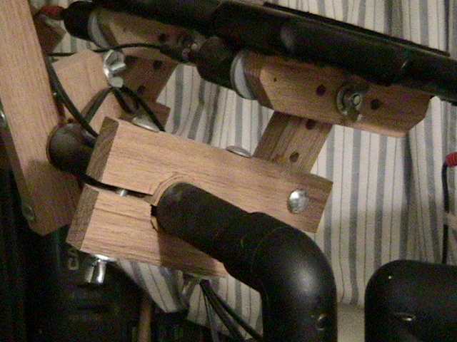
The pad holders are attached to the drumkit frame by hardwood arms. They are made of oak 1x2’s using carriage bolts and wing nuts.
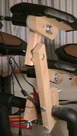
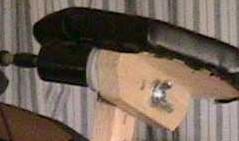
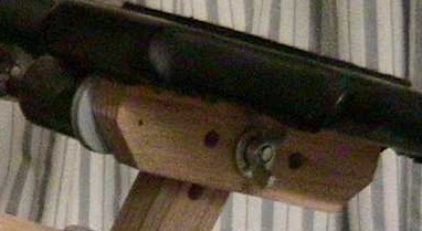
The arms clamp to the frame with a mechanism shown in the picture. A KEY feature of the drum kit is that the clamps are rubber lined and the joints of the arms have rubber gaskets (all made from the 1/4 inch rubber stock). This makes the drumkit a little "flexible" and it reduces coupling between adjacent pads which is a real problem without the rubber.
Many folks have been entertained by my mounting method for the 1/4" output jack from the drum pads. I got a bunch of film canisters for 35 mm photo film, screwed the cap to the drum pad holder, and mounted the jack on the canister and then stuck the canister onto the cap. You can sort of see this on the left side of the pads in these pictues. They're actually not all that robust and I don't know that I'd recommend them, but they were free.
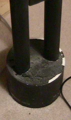
The drumkit frame is made of 1" or 1.25" PVC pipe (see previous pictures) that has been spray painted black. The feet of the frame are plastic forms filled with concrete that the PVC pipe is embedded in. Cross members are cemented to the 90 degree joints but they are NOT cemented to the uprights - that way the kit can be disassembled for moving.
Drum Frame Foot
The snare pad is mounted on a wood stand I built from plywood and oak 1 x 2's. The bass drum pad is a little plywood box that fits a bass drum pedal. The piezo is just mounted to the back of the plywood box where the beater hits. No "hollow core" technology needed there! A foam pad was covered in fabric and glued to the other side of the plywood where the bass beater actually hits to reduce the noise of impact in the room. A piece of rubber or two can work well there too. The hi hat pedal is just a keyboard sustain pedal I picked up cheap - I think it is a Yamaha.
Finished drum kit
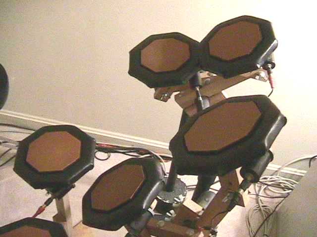
The D4’s can be had for less than $200 used, and I estimate that I spent just over $100 on the other hardware and materials. Not bad when compared to commercial electronic drumkits.
The original drumkit was used for more than a year at our church before it returned to my house. Our drummer Ed (see Ed's kit) then built two more kits (one for himself, one for church) that were used for about 3 more years until we recently returned to using acoustic drums. Ed modified my design to get a little better stick bounce by building the piezo element into Remo practice pads (that have a real drum head on them). He used the same "hollow core" approach but made a metal/foam sandwich instead of wood. Ed’s approach is somewhat more expensive but has a bit more realistic feel to it. Nevertheless, the original kit plays well and is really useful in a home studio environment. It’s not totally quiet - no one could sleep in the next room, but you can converse easily which is quite different than real drums.
| Ed's kit |